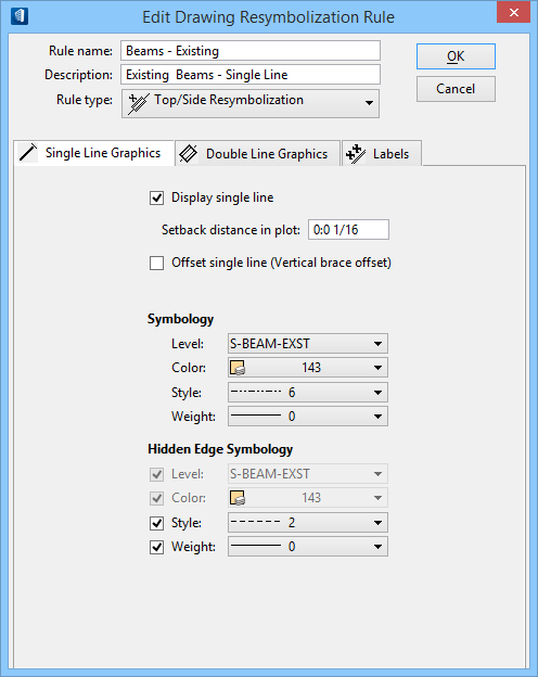
| Display single line
|
When on, enables access to single line resymbolization settings.
|
| Setback distance in plot
|
Controls the size of the gap at each end of an Structural member.
This distance is applied in addition to any cutbacks or copes on the Structural
member, ensuring an accurate drawing.The setback distance is a plotted distance
and not a model or drawing scale. This value will not change for differently
scaled drawings.
|
| Offset single line (Vertical brace offset)
|
Turn on this check box to offset the resymbolized single line for
elements using this rule. The line is offset above or below (depending on your
selection) by the value in the Distance field. This shifts the location of the
single line and is helpful if you have a situation like vertical braces in a
plan view, where a vertical brace is hidden by another element above it in the
extracted drawing.
|
| Distance
|
Key in the distance by which the single line will be
offset in the extracted drawing. This field appears only if you have turned on
the
Offset single line (Vertical brace offset)
check box.
-
Above – The single line graphic appears
offset above the actual location by the value keyed in for the distance
setting.
-
Below – The single line graphic appears
offset below the actual location by the value keyed in for the distance
setting.
|
| Symbology
|
The resymbolized single line graphics symbology is
determined with the settings in this region of the dialog.
-
Level — Sets the level for visible
single lines.
-
Color — Sets the color for visible
single lines.
-
Style — Sets the line style for visible
single lines.
-
Weight — Sets the line weight for
visible single lines.
|
| Hidden Edge Symbology
|
The resymbolized single line graphics hidden edge
symbology is determined with the settings in this region of the dialog. The
hidden edges being resymbolized are those that are covered by another item in
the drawing (a beam that is behind a crossing girder, for example). Even if you
set the symbology for hidden edges here, you must also turn on the hidden edges
option on the Forward/Reflected views settings used in the drawing composition
process.
-
Level — Sets the level for hidden single
edges.
-
Color — Sets the color for hidden single
edges.
-
Style — Sets the line style for hidden
single edges.
-
Weight — Sets the line weight for hidden
single edges.
|